Direct answer
Direct answer
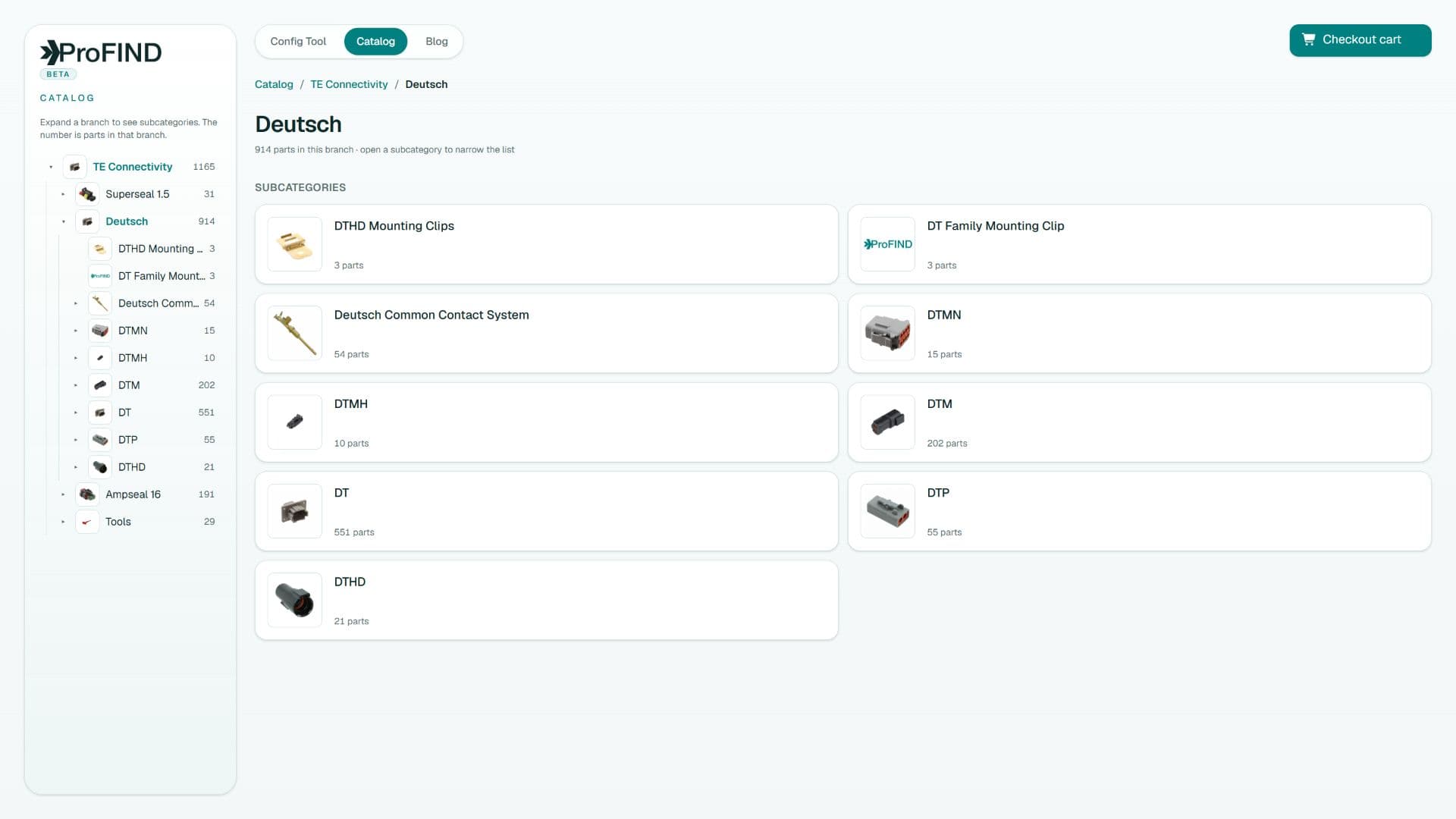
Choose DTM for compact low-current signal circuits using smaller size 20 contacts, DT for general-purpose signal and power circuits using size 16 contacts, and DTP for fewer higher-current circuits using larger size 12 contacts. Final selection must use the specific configuration’s wire range, derating data, environment, keying, and available tooling—not family-level current shorthand alone.
Key takeaways
- Contact size is the clearest first discriminator among DTM, DT, and DTP.
- Larger contacts trade circuit density and package size for greater current capability.
- The families are related but not cross-mating substitutes.
- Use actual load and thermal conditions to select the smallest suitable system.
Side-by-side engineering comparison
| Family | Typical contact size | Best starting point | Primary tradeoff |
|---|---|---|---|
| DTM | Size 20 | Dense signal and low-current circuits | Lower current per circuit |
| DT | Size 16 | General signal and moderate-power harnesses | Balanced size and capability |
| DTP | Size 12 | Higher-current circuits | Larger package and fewer positions |
This table is a selection shortcut, not a rating table; verify the exact part and application data before design release.
Choose from the circuit outward
This prevents a common inversion: selecting a convenient housing first and then forcing the circuit and wire into whatever terminal fits. Electrical and mechanical requirements should converge on the connector family together.
- List steady, transient, and fault-protected current for every circuit.
- Choose conductor size from ampacity, voltage drop, mechanical strength, and harness rules.
- Identify the connector contact size that accepts that production wire.
- Apply temperature and loaded-cavity derating.
- Select a housing family and position count with routing and service margin.
Packaging and serviceability
DTM supports compact multi-circuit interfaces where space and signal density dominate. DT is often the practical middle ground for mixed control loads. DTP is useful when a small number of circuits need larger conductors and contacts. If the design contains both low-current signals and high-current loads, separate interfaces may produce a more robust harness than forcing one family to cover every circuit.
Consider hand-tool availability, contact removal, technician familiarity, key allocation, and spare-part strategy. A theoretically compact connector can cost more across the lifecycle if it is difficult to assemble or service correctly.
Compatibility does not cross family boundaries
A DTM housing does not become compatible with DT or DTP because the position count looks similar. Each family has its own interface and contact ecosystem. Within a family, you must still align plug/receptacle role, contact system, positions, keying, and modifications.
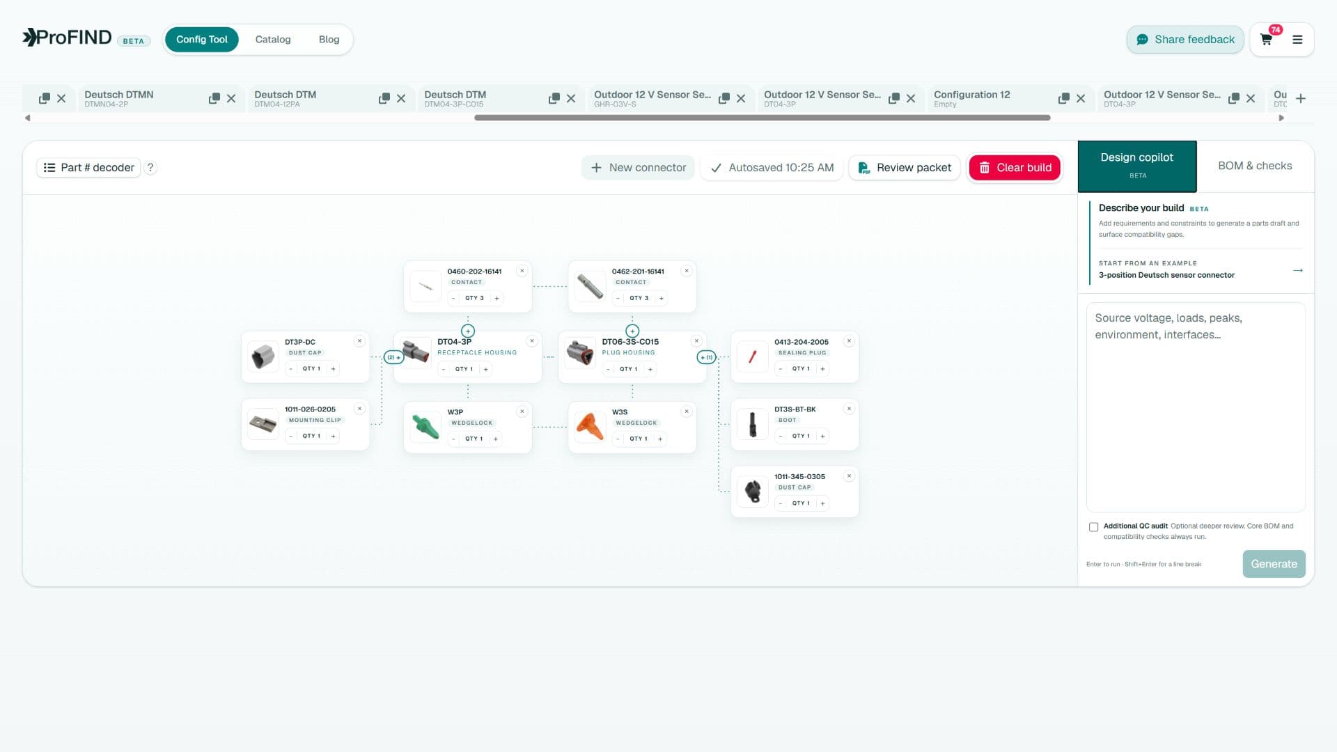
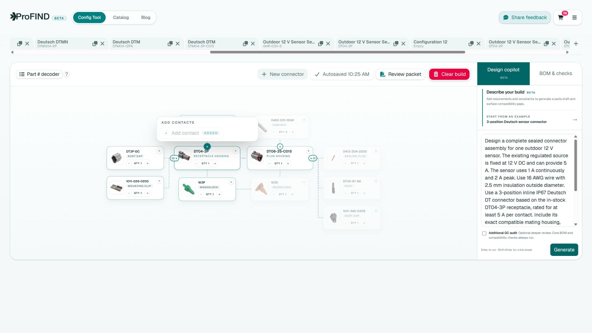
In ProFind, the product-line choice constrains the node graph before accessories are offered. That keeps a valid DT contact or wedgelock from being mistaken for a DTM or DTP part with a similar description.
A defensible selection statement
Document the decision in engineering terms: “DTM selected for twelve low-current sensor circuits on 20 AWG thin-wall wire at the specified ambient, with derating verified,” or “DTP selected for two higher-current feeds after voltage-drop and temperature-rise review.” That sentence gives a future reviewer more value than “Deutsch selected for robustness.”
Quick answers
Frequently asked questions
What is the main difference between DTM, DT, and DTP?
They use different contact sizes: DTM typically size 20, DT size 16, and DTP size 12, producing different wire, current, density, and package tradeoffs.
Can Deutsch DTM and DT connectors mate?
No. They are separate interface systems even when their housings have a similar visual language.
Should I always use DTP for high current?
Not automatically. Compare the exact contact and housing derating data, conductor size, ambient, circuit count, voltage drop, packaging, and protection requirements.
Engineering note
ProFind narrows choices and exposes compatibility reasoning. Always confirm the final assembly against current manufacturer drawings, application specifications, and your organization's validation process.

Written by
Parker Langlois
Founder of ProFind
Parker Langlois is an industrial designer and the founder of ProFind. He is building practical tools that turn connector selection, compatibility checks, and assembly planning into a clear, reviewable engineering workflow.