Direct answer
Direct answer
For a student project, select connectors by writing the circuit and environment requirements first, choosing wire from current and voltage-drop needs, selecting a connector family that accepts that wire and load, configuring exact mating housings and assembly parts, then building and testing production-intent crimps. Document the result with MPNs, cavity map, tooling, and evidence so next year’s team can maintain it.
Key takeaways
- Do not start by browsing connector kits; start with a measurable interface requirement.
- A complete BOM includes contacts, locks, seals, plugs, and tools—not just housings.
- Prototype with the same wire and crimp process you expect to use on the final system.
- Good documentation turns a one-season build into reusable team knowledge.
Turn the interface into requirements
Put unknowns in the table instead of hiding them. An explicit “insulation OD TBD” creates a task; an assumed seal chosen from AWG creates a latent failure.
- Circuit names, signal types, voltage, steady current, and transient current
- Conductor gauge, insulation diameter, shielding, and cable construction
- Indoor/outdoor exposure, water, dust, fluids, vibration, and temperature
- Inline, board, or panel interface plus available space and routing
- Expected disconnect frequency and tool access
- Budget, lead time, spare-part availability, and team tooling
A six-step capstone workflow
- Define the interface and worst-case electrical load.
- Choose wire size and insulation construction.
- Shortlist connector families that meet wire, environment, packaging, and service needs.
- Build the exact assembly: mate, contacts, locks, seals, plugs, and accessories.
- Select tooling and qualify sample crimps.
- Release the BOM, cavity map, test results, and service instructions together.
Use ProFind as a learning tool, not an answer key
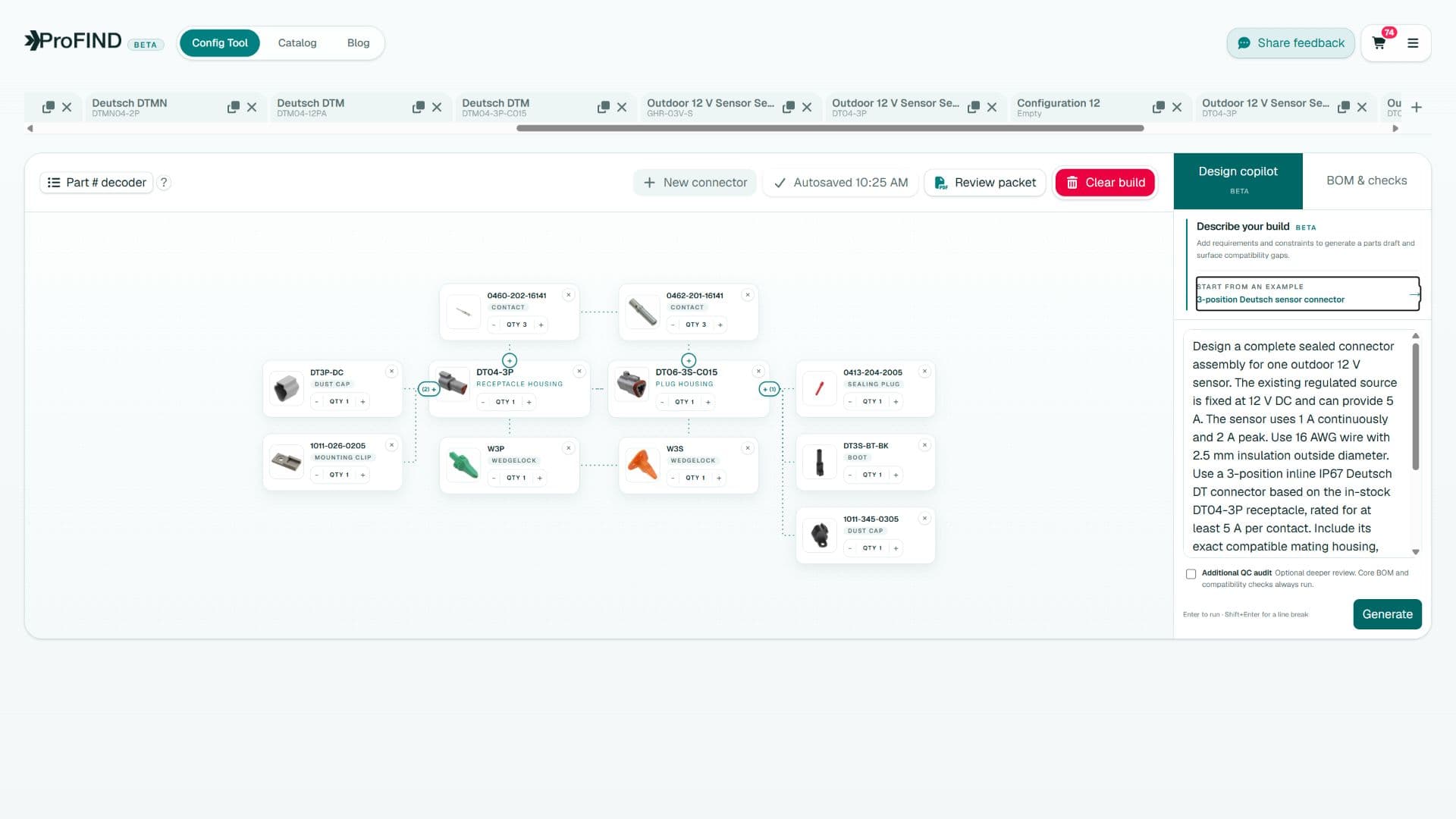
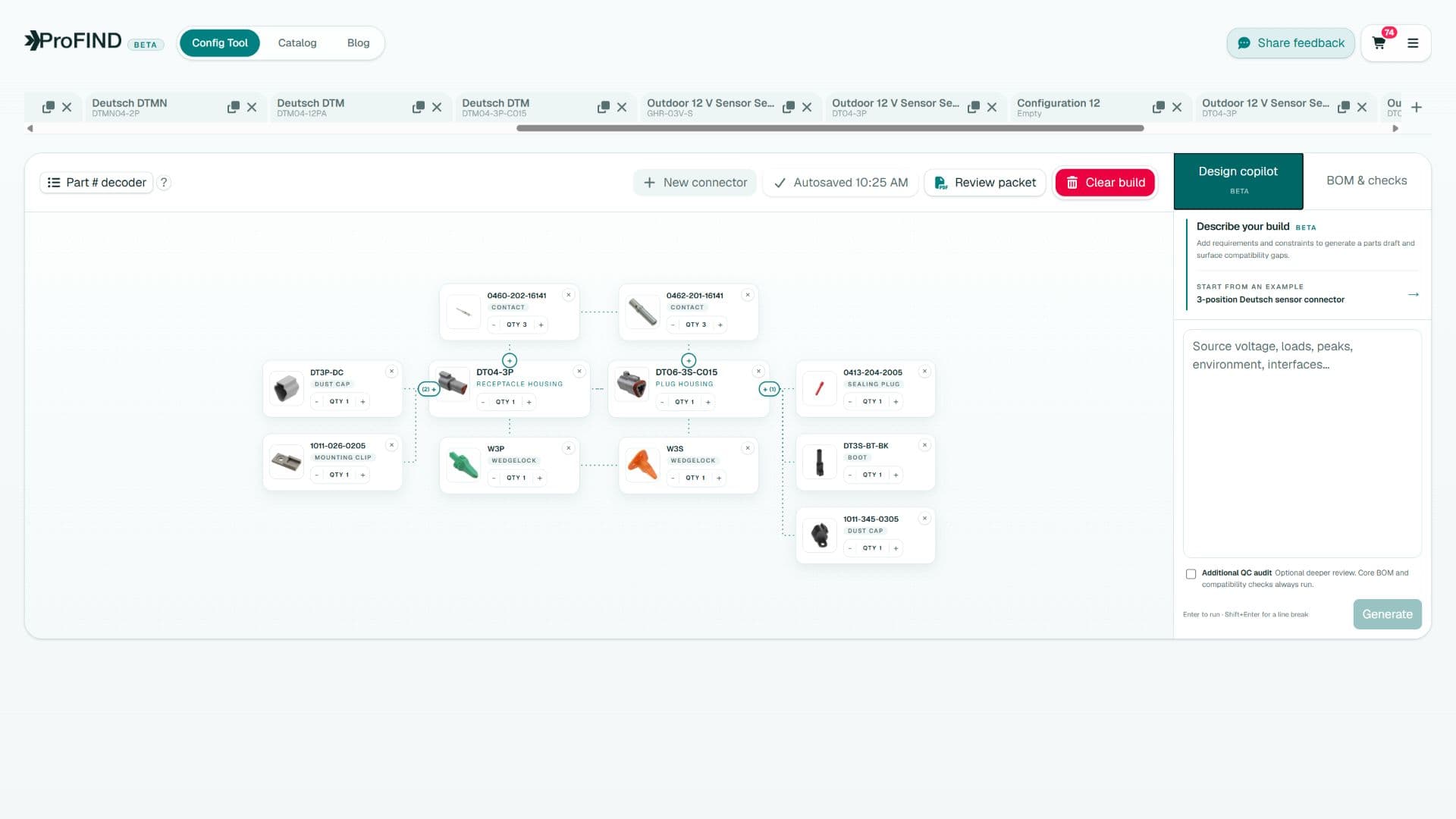
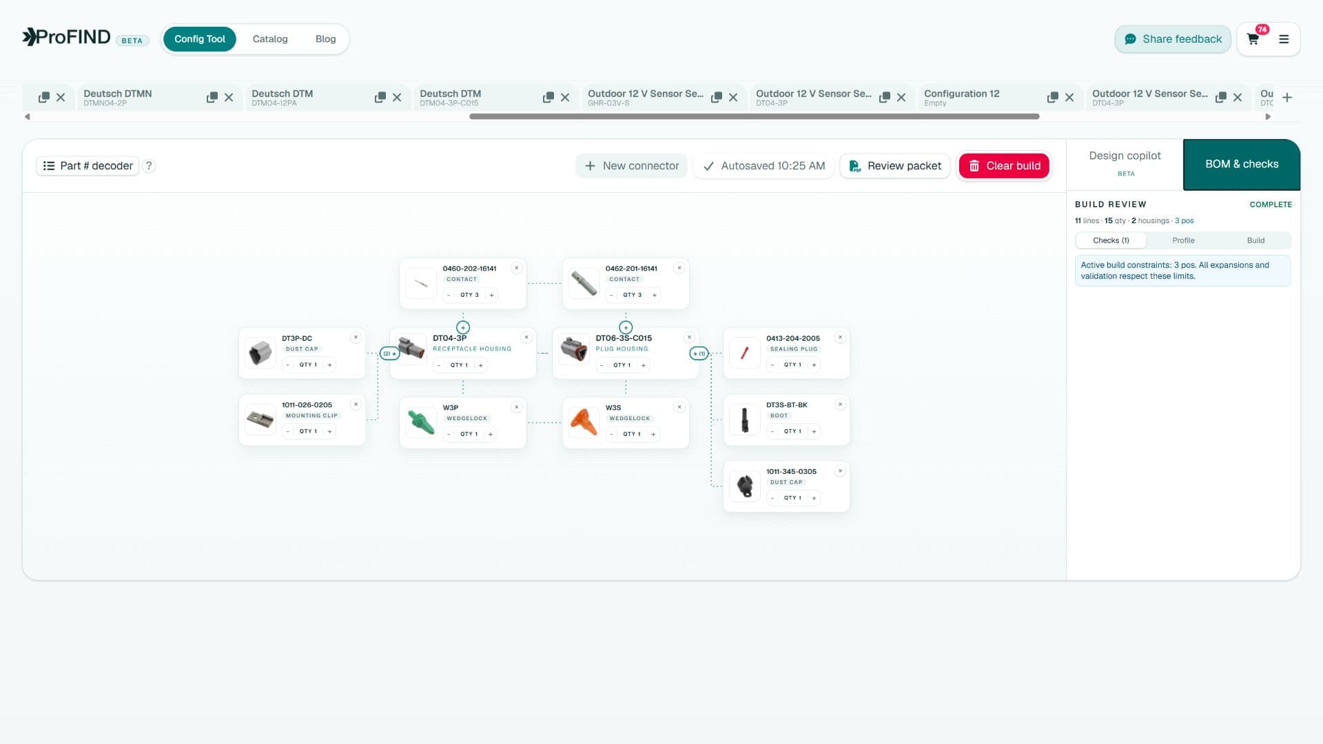
The node builder shows how parts relate, making a connector assembly easier to reason about than a pile of store pages. Design Copilot can translate a plain-language brief into a candidate graph, while the Part Decoder shows which ordering-code attributes influence compatibility.
Challenge the output: ask why the mate is valid, why the contact fits the wire, what closes unused cavities, and which document controls the crimp. The value is not only a faster part list; it is a visible engineering argument you can review with a faculty advisor.
Budget for tools and destructive samples
| Item | Why to budget it |
|---|---|
| Qualified crimp tool | Repeatable termination geometry |
| Extraction tool | Controlled rework without housing damage |
| Extra terminals and seals | Setup, practice, and destructive tests |
| Pull-test samples | Mechanical process evidence |
| Spare mated sets | Debug, repair, and competition support |
Leave a handoff another student can use
Store exact manufacturer MPNs, supplier numbers, approved alternates, cavity numbering, wire colors, crimp settings, photos of acceptable samples, and validation results. Record which connector state is sealed and how exposed halves are protected.
Before the design review, ask a teammate who did not choose the connector to rebuild one connection from the documentation. Every question they need to ask identifies a handoff gap.
A student connector design is successful when it survives both the test course and next year’s team turnover.
Quick answers
Frequently asked questions
What connectors are best for student robotics projects?
There is no universal best family. Choose from circuit current, wire, environment, vibration, package, service needs, budget, availability, and access to qualified tooling.
Can students use automotive connectors in prototypes?
Yes, when the family fits the requirements and the team can source genuine components, assemble them with controlled tooling, and verify the connection.
What connector documents belong in a capstone report?
Include the requirements, selection rationale, exact BOM, mating and cavity drawings, tooling and crimp criteria, test plan, results, and service instructions.
Engineering note
ProFind narrows choices and exposes compatibility reasoning. Always confirm the final assembly against current manufacturer drawings, application specifications, and your organization's validation process.

Written by
Parker Langlois
Founder of ProFind
Parker Langlois is an industrial designer and the founder of ProFind. He is building practical tools that turn connector selection, compatibility checks, and assembly planning into a clear, reviewable engineering workflow.